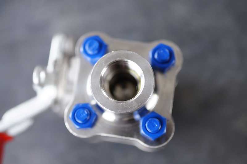
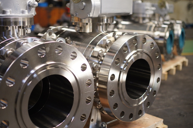
What are we talking about when we talk valve connections? Today's topic is about some common valve connection types, including flange (RF, FF, RTJ), Screw (NPT, BSPT), Weld (Butt Weld, Socket Weld) and some codes and standards for these connections.
Topics
1. Considerations for selecting valve end connection
2. Flange connection
3. Screw connection
4. Welded end connection
5. Connection types codes and standards
1. Considerations for selecting valve end connection
Once the valve has been sized, but before it can be selected, the end connections of the valve must be specified.
End connection type for specific valve should be selected with consideration of pressure/temperature ratings, materials, assembling and disassembling frequency. Additionally the end connections on valves must match piping design and specifications, piping forces that will act on the valve body must be taken into account. Purpose of the end connections is to assure rigid and leak free pipe to valve connections.
There are three common methods of connecting valves to the pipelines and fittings: flanged, threaded and welded end connection.
For general service, valve end connection selection is a simple question of whether the selected end connection type is available for the required type of valve. But when considering for demanding services, all of the above factors and some other specific for certain applications must be taken into consideration. This can mean considering factors as erosion, corrosion, toxicity, contamination, fire hazard, human health hazard etc. Such requirements can come due to specific operating requirements for the certain valve application and thus can rise the valve price significantly.
End connections on valves are usually specified by the piping design engineer and it is preferable to match the piping design specifications. However, the piping designer does not determine the forces generated in the piping by valve action and must be informed of these by the valve engineer. Proper valve end connections can then be selected according to the strength required to maintain gasket sealing stress under all operating conditions and the degree of gasket seal tightness considering:
2. Flange connection
Flange connection type is easiest connections to be installed or uninstalled from a pipeline. Arguably these are the most commonly used end connections at present.
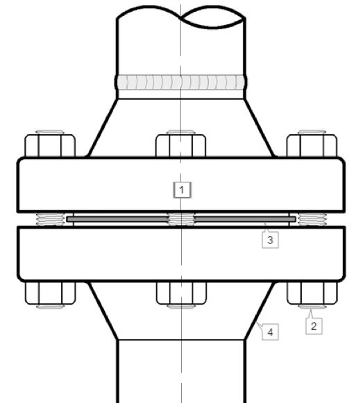
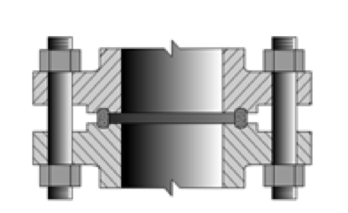
Figure 1. (1) Pipeline flange; (2) Bolt; (3) Gasket; (4) Valve flange
These are usually available in sizes from 1/2” (DN15) onwards. An important point to be mentioned about these types of end connections is that they are secured with bolts, where number of bolt range from 4 to 8, up to 12 and 16 for higher nominal size. For this reason, this type of connection needs less tightening torque than what a threaded end connection requires. Hence, flanged end connections can be effectively used for various types of valves. As these are fastened to the pipe flanges, assembling or disassembling them is quick and easy.
To ensure a tight seal, a gasket is usually fitted between the machined facing of the flanges. The type of gasket can be non-metallic, metallic or a combination of non-metallic/metallic materials, depends upon service conditions and the type of flange.
There are several types of flanges most widely used today: Raised Face Flange – RF, Flat Face Flange – FF, Ring-Type Joint Flange –RTJ.
2.1 Raised Face Flange – RF
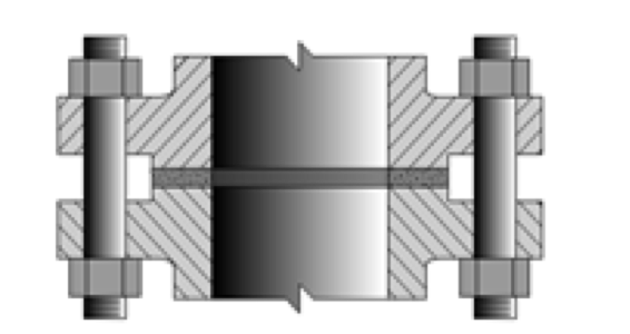
Most common type used in process plant applications are the Raised Face flanges. This flange is preferred because its raised gasket surfaces above the bolting circle face as Figure 2 shows. This design allows the use of a wide combination of gasket designs, including flat ring sheet types and metallic composites such as spiral wound and double jacketed types.
Figure 2. RF flange
The design intention for RF flange is to concentrate more pressure on a smaller gasket area and thereby increase the pressure containment capability of the joint.
2.2 Flat Face – FF
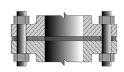
The Flat Face – FF flange (Fig.3) has a gasket surface that is in the same plane as the bolting circle face. Applications using flat face flanges are frequently those in which the mating flange or flanged fitting is made from a casting (e.g. bronze and iron valves). Additionally, according to ASME B31.1, when connecting flat face cast iron flanges to carbon steel flanges, the raised face on the carbon steel flange must be removed, and that a full face gasket is required.
Figure 3. FF flange
In general important thing to note is that none of these three most widely used flange types are interchangeable between types.
2.3 A Ring-Type Joint – RTJ
A Ring-Type Joint can also have a raised gasket face with the difference being the ring groove machined in this face. This groove will accommodate a steel ring gasket for flange mating
Figure 4. Ring - type joint
The RTJ flanges are used in high pressure applications, typically for #600 and higher and/or high temperature ratings above 800°F . For gasket it is widely used style R ring that is manufactured in accordance with ASME B16.20 used with ASME B16.5 flanges. R type gaskets (Fig.5) mostly come in oval shape but there are also octagonal configurations.
Figure 5. R type gasket
3 Screw connection
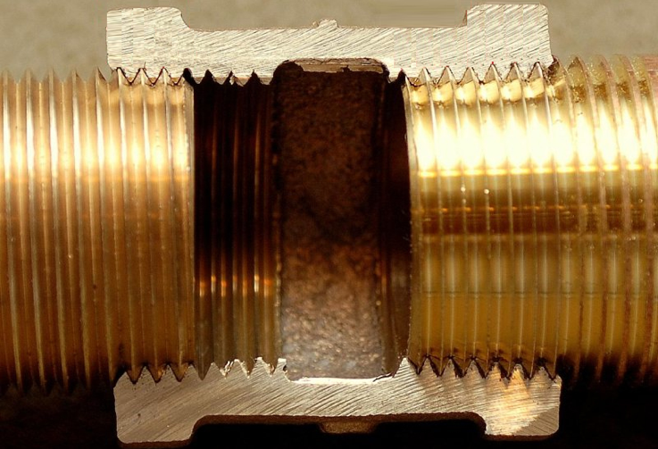
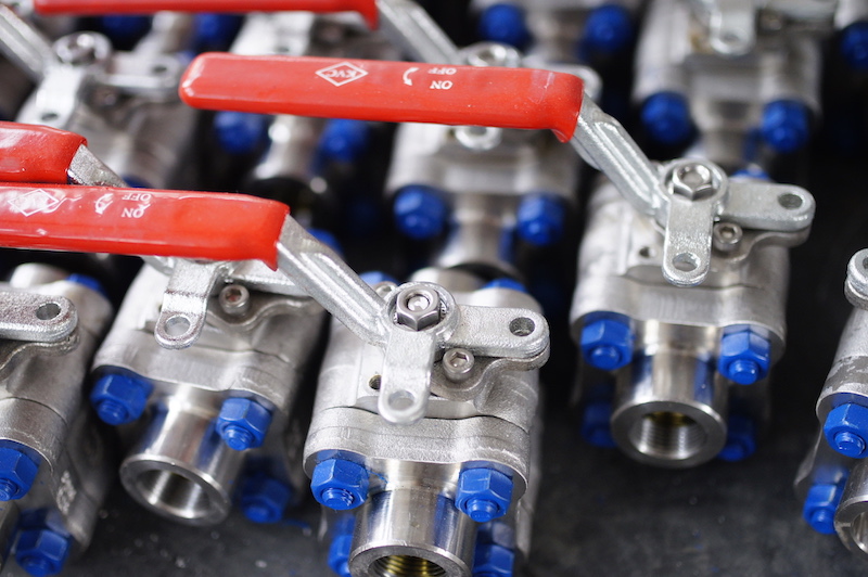
Majority of valves with screwed end connections are produced with female pipe threads, although for some special purposes they can come with other types of screw connections.
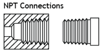
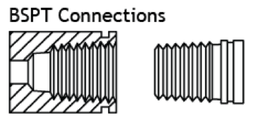
Figure 6. NPT and BSPT connection
Screwed end connections are mostly used in small valves, offer more economy than flanged ends. It is widely used for bronze/brass valves and to a lesser extent in iron and steel valves. The threads usually specified are tapered female NPT (or alternatively as BSPT which slightly differs in taper angle 55⁰ instead degrees instead of 60⁰ as it is for NPT) on the valve body.
While NPT enforces taper-to-taper connections, the pressure-tight joint is made on the threads, there is NPS threads which come as parallel-to-parallel connections. For NPS connection pressure tight joint is made by compressing a grummet or gasket against the end face of a valve.
Figure 6. NPS (left) and NPT (right) connection
Screw connection style is usually limited to valves not larger than 2" (in rare cases up to 6"), is not recommended for elevated temperature service. Valve maintenance might be complicated by screwed end connections if it is necessary to take the body out of the pipeline because the valve cannot be removed without breaking a flanged joint or union connection to permit unscrewing the valve body from the pipeline.
4 Welded end connection
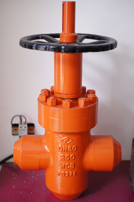
Welded ends on valves are leak tight at all pressures and temperatures as pressure/temperature of valve material and are typically used for valves with higher diameter. Welding ends come in two styles socket welding – SW and butt welding – BW .
Figure 7. SW connection
4.1 Socket weld end – SW
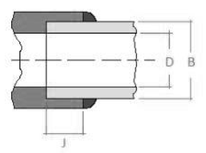
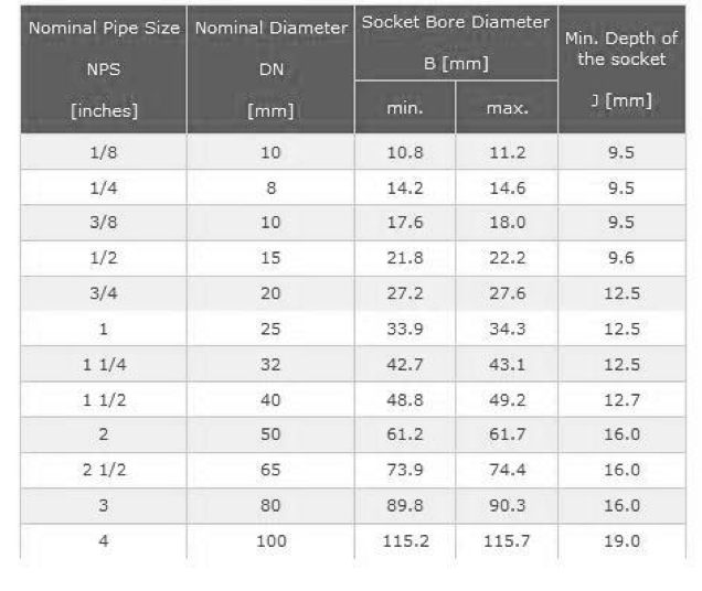
The SW ends (as shown on Figure 7) are prepared by boring in each end of the valve a socket with an inside diameter slightly larger than the pipe outside diameter. The pipe slips into the socket where it butts against a shoulder and then joins to the valve with a fillet weld. SW ends in a given size are dimensionally the same regardless of pipe schedule.
Figure 8. SW connection dimensions
4.2 Butt weld end – BW
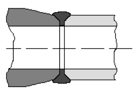
The BW ends are prepared by beveling each end of the valve to match a similar bevel on the pipe. The two ends are then butted to the pipeline and joined with a full penetration weld. This type of joint is used on all valve styles and the end preparation must be different for each schedule of pipe.
Butt weld ends are used only on steel valves, normally in sizes 2" and upwards, for the higher pressure/temperature applications in pipelines which do not require frequent dismantling.
In general welded end valves are more difficult to take from the line and are obviously limited to wieldable materials thus their initial cost is more economical than in other types of connections.
Figure 9. BW connection
5 Connection types codes and standards
End connection types are determined by local and international codes and standards. Generally mostly are used US and EU standards. For more information about end connection types and dimensions for certain connection type and size, one should refer to the following standards:
- ASME B1 6.34 Valves-flanged, threaded, and welding end
- ASME B16.5 - Pipe flanges and flanged fittings
- EN 1092 Flanges and their joints — Circular flanges for pipes, valves, fittings and accessories, PN designated
While both of the standards rely on the same physical/mechanical properties to determine allowable pressure/temperature ratings for different sizes and materials of connections some of the differences between the ASME and EN codes is in designation of the PT ratings. While EU standards use Nominal Pressure designation (PN), ASME uses Class designation. Basic conversion from Class to PN is shown in Figure 10.
Figure 10. Class to PN conversion table
This article is just a brief introduction to valve connections, if you have any question or need further information, please contact us via mail sales@wfecn.com or direct call +86 (577) 5775 5599.
